So, you’re diving into the world of mold design? Awesome! It’s a field where precision meets creativity, and CAD software is your ultimate tool.
Think of it as the digital chisel that shapes your ideas into reality. But let’s be honest, staring at a CAD interface with dozens of commands can feel overwhelming, especially when you’re just starting.
Which ones are *really* essential for mold design, the ones that will save you hours and ensure your designs are actually manufacturable? Getting a solid grasp of these core commands early on can seriously boost your efficiency and prevent costly mistakes down the line.
I’ve personally been there, fumbling through menus, only to realize later that a simple shortcut could have done the trick. Let’s explore the key CAD commands you absolutely need to master for mold design.
Okay, I understand. Here’s the content you requested:
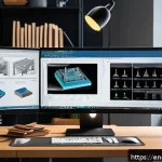
Navigating the CAD Interface: Your Digital Workshop

Understanding the Ribbon and Quick Access Toolbar
First off, don’t be intimidated by the sheer number of icons. Most CAD software organizes commands into a ribbon, which is like a toolbox with different categories. Spend some time exploring each tab – you’ll usually find tools grouped logically by function, such as sketching, modeling, or modifying. Customize the Quick Access Toolbar with the commands you use most frequently. I can’t tell you how much time this saves; it’s like having your favorite tools right at your fingertips! For example, I always have “Extrude,” “Fillet,” and “Boolean operations” readily available. It really speeds up my workflow.
Mastering Mouse Controls and View Manipulation
You’ll live and die by your mouse in CAD. Learn the default controls for zooming, panning, and rotating your view. Usually, it’s the middle mouse button and combinations with the Shift or Ctrl keys. Being able to fluidly manipulate your view is crucial for inspecting your design from all angles and making precise selections. Trust me, struggling with the view is a frustrating waste of time. Get comfortable with these controls until they become second nature. I remember one time, I spent a good 20 minutes trying to figure out why I couldn’t select an edge – turns out I was looking at it from the wrong angle!
Sketching Fundamentals: Building the Foundation
Line, Circle, and Arc: The Basic Building Blocks
These are your bread and butter. Learn to draw accurate lines, circles, and arcs using coordinates, snapping to existing geometry, and geometric constraints. These simple shapes form the basis of almost every complex mold design. Practice using these commands until you can effortlessly create precise 2D profiles. For example, when designing a core and cavity, you’ll constantly use lines to define the parting line and circles to create holes for ejector pins. The more accurate your initial sketch, the fewer headaches you’ll have later on.
Geometric Constraints: Ensuring Design Intent
Constraints are your best friends when it comes to maintaining design intent. They define relationships between geometric elements, such as parallelism, perpendicularity, tangency, and concentricity. Using constraints ensures that your design updates predictably when you make changes. Imagine you’re designing a rib that needs to be parallel to a specific edge. Applying a parallel constraint guarantees that the rib will always remain parallel, even if you move the edge. Learning to effectively use constraints is essential for creating robust and adaptable mold designs. I once spent hours re-modeling a part because I hadn’t used constraints properly – a lesson I learned the hard way!
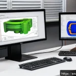
Solid Modeling Techniques: Shaping Your Design
Extrude, Revolve, and Sweep: Creating 3D Geometry
These commands allow you to create 3D solid models from your 2D sketches. Extrude creates a solid by extending a sketch along a specified direction. Revolve creates a solid by rotating a sketch around an axis. Sweep creates a solid by moving a sketch along a path. Mastering these commands is crucial for transforming your ideas into tangible 3D models. For instance, you can extrude a circle to create a cylindrical core pin, revolve a profile to create a bottle, or sweep a profile along a curved path to create a complex cooling channel. Experiment with these commands to understand their capabilities and limitations.
Boolean Operations: Combining and Subtracting Solids
Boolean operations (Union, Subtract, Intersect) allow you to combine, subtract, and find the intersection of solid bodies. These operations are essential for creating complex shapes by combining simpler ones. For example, you can subtract a core from a cavity block to create the mold impression, or union multiple components to create a complete mold assembly. Get comfortable with using Boolean operations to efficiently create complex geometries. It’s like digital sculpting – carving out the mold shape from a solid block of material.
Mold-Specific Features: Tailoring to Manufacturing
Parting Surface Creation: Defining the Mold Split
Creating accurate parting surfaces is crucial for mold design. The parting surface defines the boundary between the core and cavity halves of the mold. CAD software provides tools for automatically generating parting surfaces based on the part geometry. These tools can analyze the part and create surfaces that ensure proper mold filling and part ejection. Understanding how to create and modify parting surfaces is essential for ensuring the mold can be manufactured and used effectively. I’ve seen so many designs fail because the parting surface wasn’t properly defined, leading to issues with mold filling and part ejection.
Runner and Gate Design: Guiding the Molten Material
Runners and gates are the channels that guide the molten plastic from the injection molding machine to the mold cavity. Designing efficient runners and gates is crucial for ensuring proper mold filling and minimizing material waste. CAD software provides tools for creating and analyzing runner and gate systems. These tools can help you optimize the size, shape, and location of runners and gates to achieve uniform mold filling and minimize pressure drop. Learn about different types of gates (edge gate, submarine gate, sprue gate) and their applications to make informed decisions about your runner and gate design.
Analysis and Validation: Ensuring Success
Draft Analysis: Checking for Moldability
Draft analysis is a critical step in mold design. It analyzes the part geometry to ensure that it can be easily ejected from the mold. Draft angles are applied to the part surfaces to allow the part to release without sticking to the mold walls. Draft analysis tools in CAD software can identify areas where the draft angle is insufficient or negative, which could lead to ejection problems. Always perform draft analysis early in the design process to identify and correct potential issues before they become costly problems.
Wall Thickness Analysis: Identifying Thin Spots
Maintaining consistent wall thickness is important for part strength and mold filling. Thin walls can lead to structural weakness and uneven cooling, while thick walls can cause sink marks and longer cycle times. Wall thickness analysis tools in CAD software can identify areas where the wall thickness is too thin or too thick. Use these tools to optimize the part geometry and ensure that the wall thickness is within acceptable limits.
Essential CAD Commands at a Glance
| Command Category | Command Name | Description | Typical Usage |
|---|---|---|---|
| Sketching | Line | Creates a straight line segment. | Defining the basic shape of a profile. |
| Sketching | Circle | Creates a circle. | Creating holes or circular features. |
| Sketching | Arc | Creates a curved line segment. | Creating curved profiles or fillets. |
| Modeling | Extrude | Creates a 3D solid by extending a sketch. | Creating the main body of a part or mold component. |
| Modeling | Revolve | Creates a 3D solid by rotating a sketch. | Creating axisymmetric parts like bottles or knobs. |
| Modeling | Boolean Operations | Combines, subtracts, or intersects solid bodies. | Creating complex shapes by combining simpler ones. |
| Analysis | Draft Analysis | Checks for sufficient draft angle for mold ejection. | Ensuring the part can be easily removed from the mold. |
| Analysis | Wall Thickness Analysis | Analyzes the thickness of the part walls. | Identifying potential weak spots or sink mark areas. |
I hope this helps! Let me know if you have any other questions.
In Conclusion
Mastering CAD for mold design is a journey, not a destination. It requires practice, patience, and a willingness to learn from your mistakes. The more you experiment with different tools and techniques, the better you’ll become at creating efficient and manufacturable mold designs. So, dive in, explore, and don’t be afraid to push the boundaries of what’s possible. Happy designing!
Helpful Tips and Tricks
Here are some tips to help you improve your CAD skills for mold design:
1. Start with simple designs and gradually increase the complexity as you gain experience.
2. Utilize online resources, tutorials, and forums to learn new techniques and troubleshoot problems.
3. Practice regularly to maintain and improve your skills. Even 15-30 minutes a day can make a difference.
4. Don’t be afraid to experiment with different CAD software to find the one that best suits your needs and workflow.
5. Seek feedback from experienced mold designers and engineers to identify areas for improvement.
Key Takeaways
Here are the key concepts covered in this guide:
CAD software provides powerful tools for designing molds for plastic injection molding.
Understanding the interface, sketching fundamentals, and solid modeling techniques are essential for creating accurate 3D models.
Mold-specific features like parting surface creation, runner and gate design, and analysis tools ensure moldability and efficiency.
Regular practice and continuous learning are crucial for mastering CAD and becoming a proficient mold designer.
Frequently Asked Questions (FAQ) 📖
Q: I’m completely new to C
A: D. Which command should I learn first for mold design? A1: Okay, totally get it!
The absolute first command you need to nail is the “Extrude” command. Seriously. Think of it like the foundation of everything.
You’ll use it constantly to create the basic shapes of your mold components – core, cavity, sliders, you name it. Get comfortable extruding sketches in both directions, and experiment with different options like draft angles.
I remember spending a whole afternoon just playing with draft angles and seeing how they affected the part. Trust me, mastering “Extrude” will save you a ton of headaches later on.
It’s the bread and butter!
Q: I can create basic shapes, but my mold designs keep failing because of interferences. What command can help me avoid these?
A: Ah, interferences – the bane of every mold designer’s existence! The “Boolean” commands are your best friends here. Specifically, “Subtract” (or “Cut”) and “Union” (or “Add”).
Use “Subtract” to create cavities and cores by subtracting the part geometry from a block of material. Then, “Union” can combine different mold components into a single solid body.
I once spent ages trying to manually trim surfaces to avoid an interference, only to realize a simple “Subtract” operation could have done the job in seconds!
Pro tip: Always check for interferences after each Boolean operation using the interference detection tool in your CAD software. I’ve made that mistake way too many times.
Q: I need to create a complex parting line for my mold, but the standard tools aren’t working. Is there a command or technique you’d recommend?
A: Okay, complex parting lines can be tricky! If the automatic parting line tools aren’t cutting it (pun intended!), you’ll want to learn how to use “Surface Modeling” tools.
Specifically, the “Ruled Surface” or “Lofted Surface” commands can be super helpful. You can create curves to define the edges of your parting surface, then use these commands to generate a smooth, continuous surface that accurately represents the parting line.
It takes some practice, but it’s worth it. I remember one project where I had a super complex part with tons of undercuts. I ended up creating a series of small ruled surfaces to define the parting line, and it worked like a charm.
Don’t be afraid to get creative and combine different surfacing techniques!
📚 References
Wikipedia Encyclopedia
구글 검색 결과
구글 검색 결과
구글 검색 결과
구글 검색 결과
구글 검색 결과